
While you may need to troubleshoot a circuit that used to work and now doesn’t, the emphasis here is how to troubleshoot a design when you have your first PCB made. While you may be fortunate and everything works perfectly first time, there is often a need for some troubleshooting with a new design. The design may be defective or there may be errors in the drawing or PCB layout. Tracking down and fixing problems requires a logical approach as well as sometimes having to revisit your expectations and assumptions. If you look at electronics forums such as EDAboard.com you will find a number of posts which concern a circuit that has been built but isn’t working as expected. A key part of an electronics engineer’s skills will be finding out why.
I have come across a few talented designers who cannot actually troubleshoot their own designs. I am not sure why that would be the case but there is a different thought process when trouble shooting. While you may start working forwards tracing signals you then have to start looking backwards to where you may have already looked “… that voltage should be 1.2V but it is 2.5V so what could cause that?”.
The first step in testing is usually to check that the power supply voltages are correct. If you are powering the circuit from a bench power supply then presumably that voltage will be correct but you may derive other voltages from it, so they should be checked. A bench power supply with a display of the current consumption is useful so you can see if the circuit is taking roughly the correct current.
An example of a common problem with an opamp circuit is shown below.
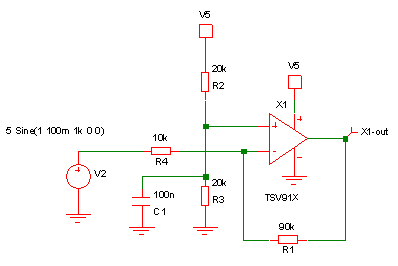
This is a simple opamp based DC amplifier with a gain of 10 running from a single supply voltage. If you applied a 100mV sine wave input signal centered around 1V, as shown, the output signal would not be 1V sine wave. Probing the circuit you would find that the output is stuck at 5V. Assuming that you don’t spot the problem straight away you would need to probe the circuit to help diagnose the problem. If the output of an opamp is not what you expect then you need to work backwards and look at the inputs. In this case the non-inverting input is at 2.5V and the inverting input is at 1.4V with a sine wave on it.
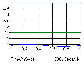
With a working opamp circuit the inverting and non-inverting input should track each other very closely. In this case they obviously aren’t doing that. Fixing the non-inverting input at 2.5V is the problem because the input voltage is nominally 1V and even with the opamp output voltage at 5V it cannot raise the inverting input to 2.5V with those resistor values. Changing R3 to 5k so the non-inverting input is at 1V will fix the problem although as the output will be centered around 1V you will not be able to use the full 5V output range of the opamp.
Take another simple example below:
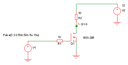
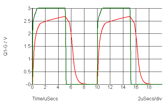
If you built this simple switch to turn on a load resistance of 10 ohms at 100kHz from a 3V logic signal you will find it doesn’t work very well. It also illustrates that a problem can have more than one solution. The performance is shown below with the red trace being the MOSFET drain voltage:
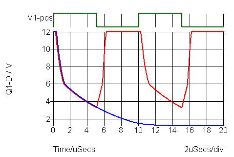
The transistor isn’t turning on very quickly and it is not turning on fully. You will notice that the transistor drain voltage is still reducing when the gate voltage returns to zero so that should give a clue that the circuit isn’t fast enough rather than a static problem. If you slow down the input clock (green trace) you will see that the drain voltage is closer to zero volts after 10µs (blue trace). Slowing down the clock would have been one of the possible tests in faultfinding the circuit – the clue to noticing that is the fact that the turn on looks slow and is not stable by the time the gate voltage returns to 0V.
With a transistor with a low threshold voltage you still need to exceed the threshold voltage by a sufficient margin so that the transistor turns on fully to minimize heat dissipation. The transistor transconductance from the datasheet should be used to determine how much excess gate voltage you need, or the graphs from the datasheet. Beware that graphs are often “typical” values and you need to design for a worst case, also bearing in mind temperature.
There isn’t a lot of circuitry to probe for troubleshooting but the first hint was at the output (drain) voltage so if you look at the voltage on the MOSFET gate you will see that it doesn’t quite reach 3V (red trace below), although if you wait a little longer it will eventually get there. While the gate voltage being a little short of 3V doesn’t seem much, it is quite significant because it is only the gate voltage above the threshold that is doing the work of driving the transistor on. Reducing the gate series resistor will improve things (green trace). This assumes that reducing the resistor is possible – it may be inherent in your drive circuitry.
Other possible improvements would be to increase the gate drive voltage to, say, 5V or change the transistor for one with a higher transconductance, lower threshold voltage and/or lower gate capacitance. All of these have the potential for improving the speed and power dissipation.
An important factor in trouble shooting is to probe the circuit and compare it with what you expect at each point to track down where the circuit deviates from what you expect. Sometimes you may not have even thought in much detail about intermediate voltages but when you have a problem you need to look at them. Be aware that sometimes probing can cause problems either due to the capacitance of the probe or the resistance. With high speed or low current circuits that can make probing quite tricky. Sometimes circuits change their behavior significantly when you start probing them. Non-working circuits can start working which in itself is a very useful clue as to the cause of the problem.
Problems become trickier if there is a PCB error. Then you will be scratching your head wondering why the voltages don’t make sense and that can be tricky if the cause is a PCB error or faulty component. When you are certain that the design is correct you then need to look for other errors – are the component values correct? are devices the correct way round? does the PCB layout really agree with the schematic you thought you had produced?
Trouble shooting involves tracing signals forwards and then looking back.